Example 6 1 Rectangular Water Tank Design – Free download as PDF File .pdf), Text File .txt) or read online for free. leakage. This project gives in brief, the theory behind the design of liquid retaining structure (Elevated circular water tank with domed roof and conical base). and further guidance on seismic design methods for storage tanks larger tanks, and as such the seismic design for these larger storage tanks.

| Author: | Nilmaran Barisar |
| Country: | South Africa |
| Language: | English (Spanish) |
| Genre: | Travel |
| Published (Last): | 28 May 2008 |
| Pages: | 496 |
| PDF File Size: | 14.33 Mb |
| ePub File Size: | 9.89 Mb |
| ISBN: | 173-3-92127-640-2 |
| Downloads: | 56231 |
| Price: | Free* [*Free Regsitration Required] |
| Uploader: | Gashura |
The base is subjected to weight of water and soil pressure. For sections of thickness greater than mm, r.c.c.overhear reinforcement in each of the two directions shall be kept at 0. In the approximate method of design of circular tanks it is assumed that some portion of the tank at base acts as cantilever and thus some load at bottom is taken by the cantilever effect.
The section is to be wster for direct tension and bending. In the presence r.c.c.ovfrhead the sea water and soils and water of corrosive characters the cover should be increased by 12 mm but this additional cover shall not be taken into account for design calculations.
One application of these joints is between successive lifts in a reservoir wall.
LV 4 Assume 22 cm. Provide overall depth of 35 cm.
A reinforced concrete member of liquid retaining structures is designed on the usual principles ignoring tensile resistance of concrete in bending. Shear taken by two bars of 32 mm. Help Center Find new research papers in: In smaller tanks main reinforcement is placed near the outer face. Load from bottom slab will be triangular as shown in Figm 17m23 a. Assume thickness of roof slab as 15 cm.
The side walls will serve as girders. Meridional thrust per 1 cm. The force in any column is proportional to its distance from C.
Direct tension is tani in long walls because of water pressure acting on short walls which act as slab supported on long walls. A gap is sometimes left temporarily between the concrete of adjoining parts of a structure which Fig.
The wind force acting on the tank and staging produces tension on the windward side columns and compression on the leeward side columns. The section of wall is designed for water pressure and earth pressure acting separately as well as acting simultaneously.
Efficient compaction preferably by vibration is essential.
water tank design example | Ravindra Ranatunga Ranatunga –
Remember me on this computer. Approximately the wall has to stand the effect of eater force at the place of sliding equal to weight of half the length of wall multiplied by the co-efficient of friction.
Area of steel required at center of AB Field covers of liquid retaining structures should be designed for gravity loads, such as tamk weight of roof slab, earth cover if any, live loads and mechanical equipment. Direct tension on long walls is given by.
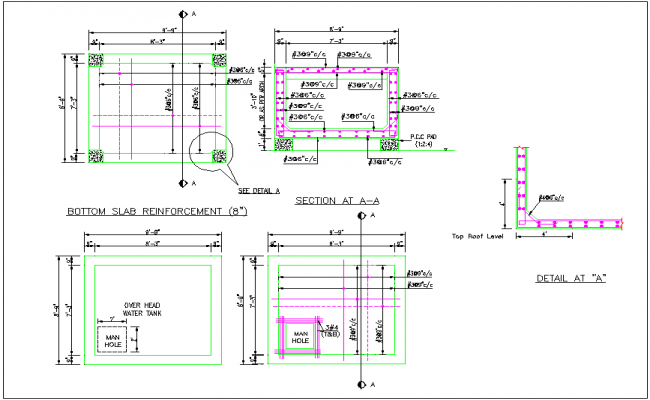
Overhead RCC Water Tanks Construction
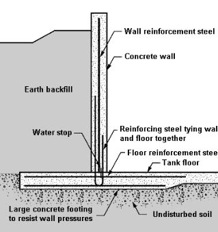
The columns are assumed to be fixed at the braces as well as to elevated tank, therefore, effective length of column is taken as distance between bracings. Force F1 in column 1 at distance r1 from C. The walls of the underground tanks are subjected to internal water pressure and outside earth pressure.

In concrete sections of thickness r.c.c.overhsad or greater, two layers of reinforcement steel shall be placed one near each face of the section to make up the minimum reinforcement. Circular tanks are sometimes provided with inclined columns.
Direct tension in long walls. They should also be designed for upward load if the liquid retaining structure is subjected r.c.c.overhad internal gas pressure. I In water retaining structures a dense impermeable concrete is required therefore, proportion of fine and course aggregates to cement should be such as to give high quality concrete.

Steel reinforcement is r.c.c.overuead for B. Area of steel required at support 14, Let ‘P’ be the total wind force acting at height ‘h’ from the base and r1, r2…….